基于eNSP的千人规模冗余型企业/校园网络设计与规划 前言简介 由于华为近几年在国内的市场越来越大,网络工程师中的组网技术的题目都由思科变为了华为,所以华为的设备还是有必要学习一下的了;本文用华为提供的eNSP模拟器模拟出了可以用于校园/企业网络的规划与设计实现。同时也可以作为大学生的学期课程设计,由于本文章只提供在设计过程中的关键技术与设计笔记(可根据以下所提供的设计与实现步骤一步一步自行实现(每一条命令都是关键的命令)
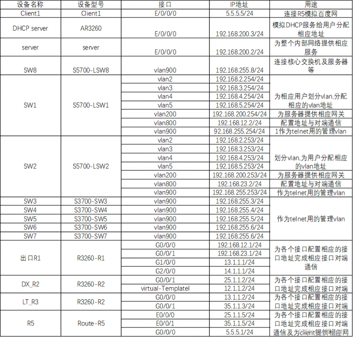
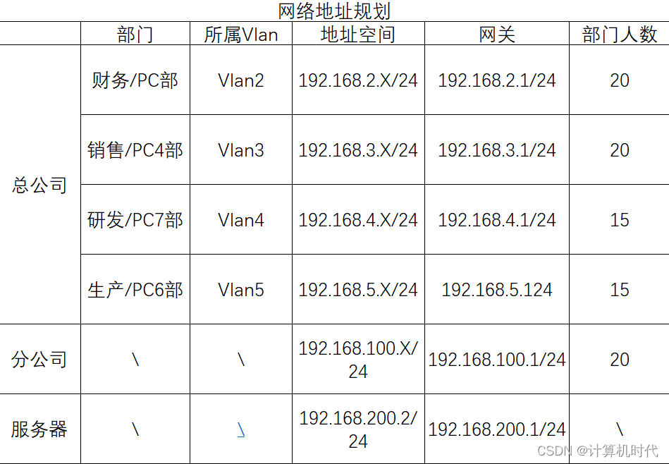
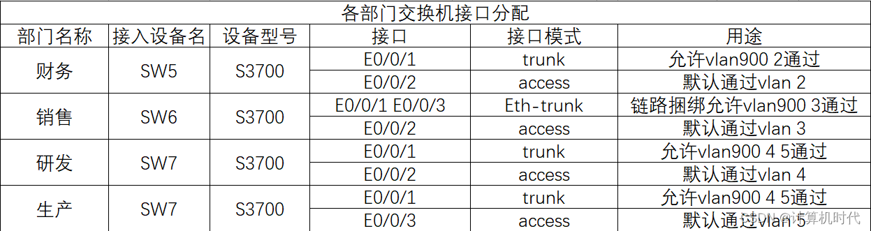
以下是相应的地址规划表及其相应规划清单(由于不好编辑就以图片形式上传)
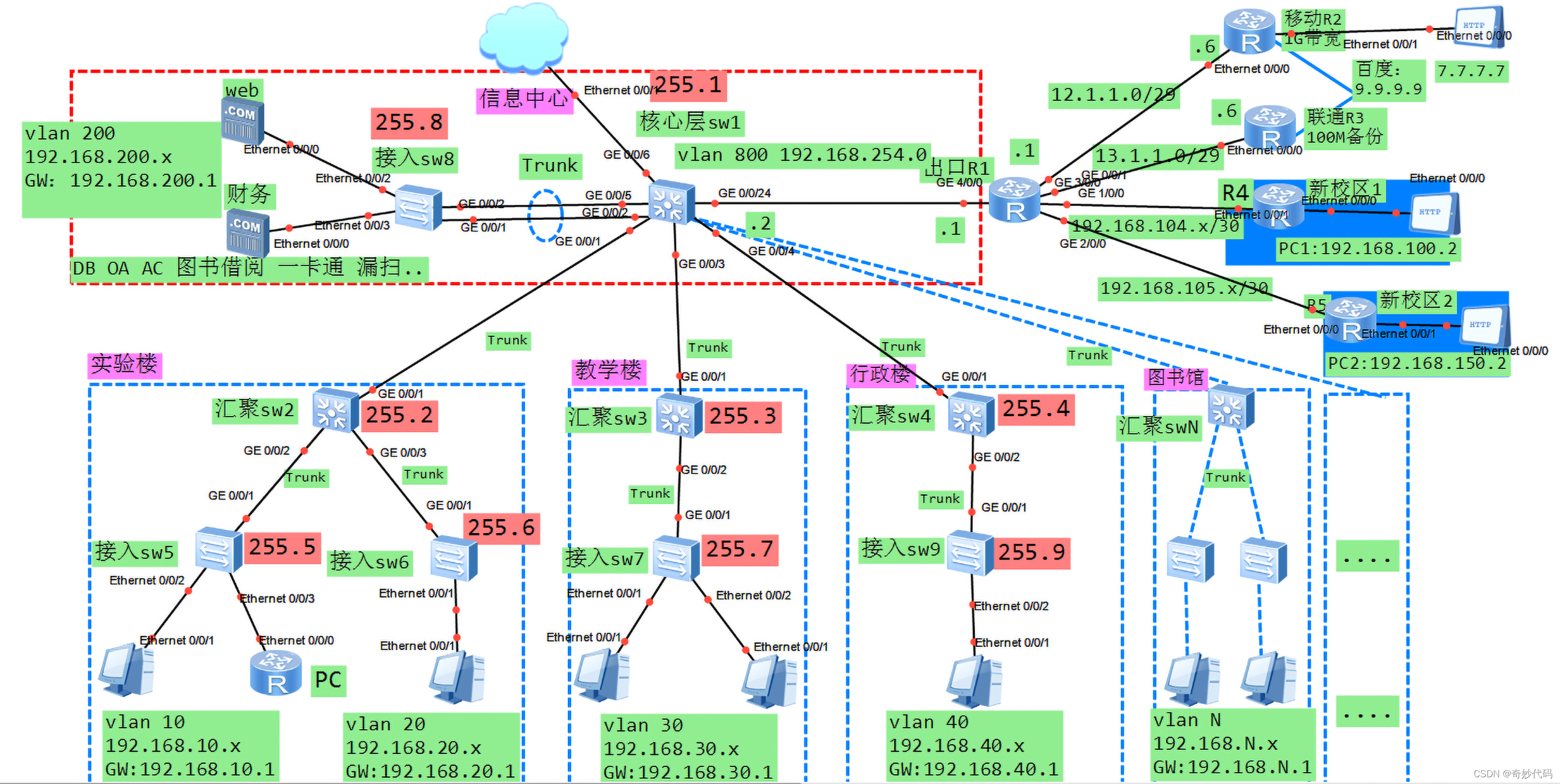
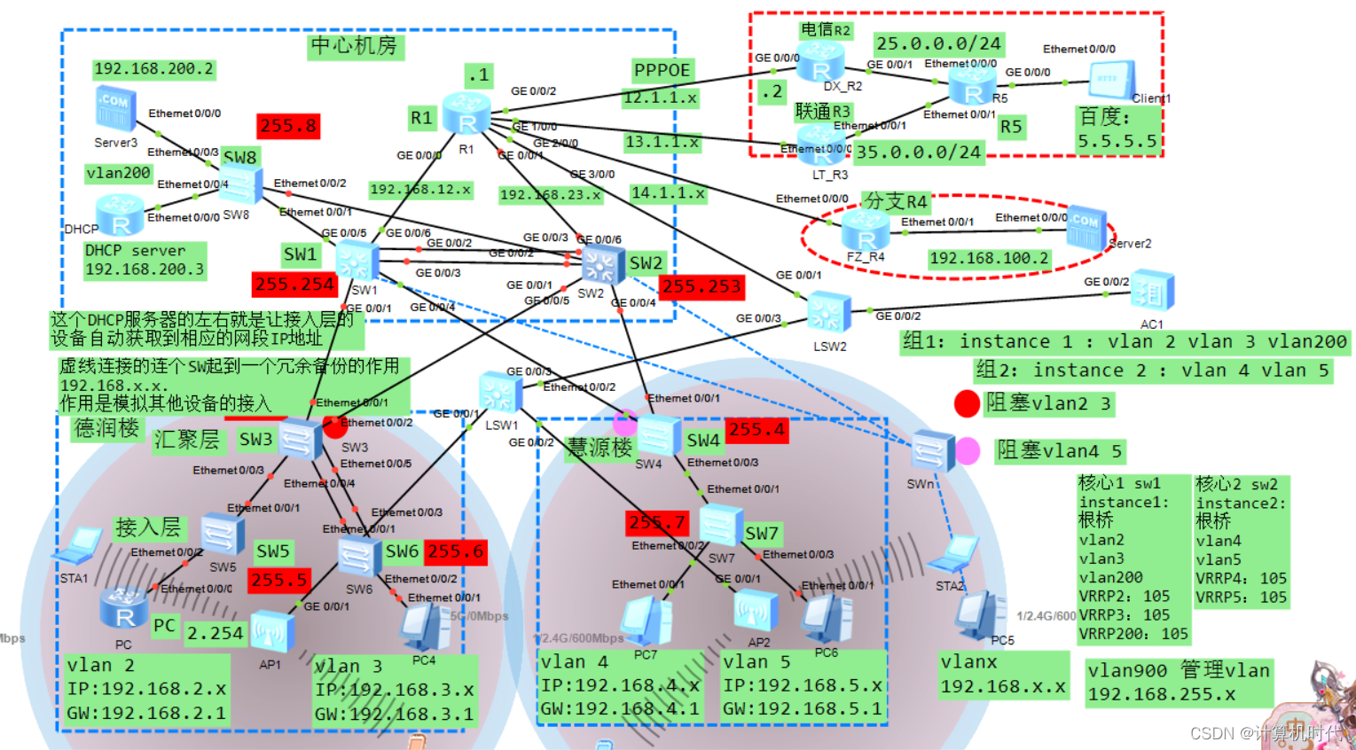
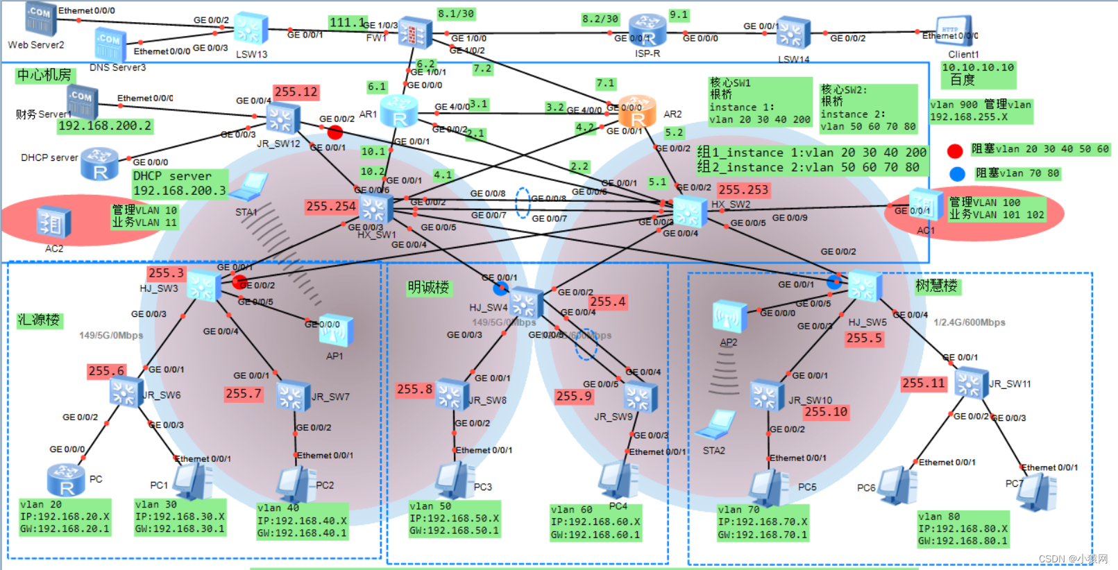
一、设计要求与设计topo图
二、需求分析 我们用到的设计思想就是根据交换机的三层架构来设计,核心层进行高速转发、冗余、均衡;汇聚层进行策略控制ACL、VLAN、Qos、分组过滤、路由选择、组播管理;最后的接入层给用户接入,多端口、用户访问控制;利用VRRP_MSTP对网络链路和设备进行冗余备份和负载均衡;设置了两个出口,电信用PPPoE拨号上网(比较廉价且不用就浪费了)
三、设计要求与前提 1)提前好由华为提供的eNSP模拟器软件(安装eNSP的前提需要先安装:VirtualBox、WinPcap、Wireshark这个三个软件作为底层的软件)
四、网络topo分析及其规划 网络拓扑(Network Topology)结构是指用传输介质互连各种设备的物理布局。指构成网络的成员间特定的物理的即真实的、或者逻辑的即虚拟的排列方式。如果两个网络的连接结构相同我们就说它们的网络拓扑相同,尽管它们各自内部的物理接线、节点间距离可能会有不同。网络设计中冗余备份和负载均衡的核心技术就需要用到VRRP+MSTP关键技术;用户自动获取IP地址当然需要开启DHCP(集合负载均衡这要求使用的时候DHCP中继为用户分配IP地址)
五、设计与实现
1、VLAN Trunk配置
1
2
3
4
5
6
7
8
9
10
11
12
13
14
15
16
17
18
19
20
21
22
23
24
25
26
27
28
29
30
31
32
33
34
35
36
37
38
39
40
HJ_SW3: <Huawei>sy [Huawei]un in en [Huawei]sysname HJ_SW3 [HJ_SW3]int Eth-Trunk 1 [HJ_SW3-Eth-Trunk1]mode lacp-static //聚合模式选择lacp-static模式 [HJ_SW3-Eth-Trunk1]trunkport e0/0/4 //加入交换机上相应的端口 [HJ_SW3-Eth-Trunk1]trunkport e0/0/5 ------------------------------------ JR_SW6: <Huawei>sy [Huawei]un in en [Huawei]sysname JR_SW6 [JR_SW6]int Eth-Trunk 1 [JR_SW6-Eth-Trunk1]mode lacp-static [JR_SW6-Eth-Trunk1]trunkport e0/0/1 [JR_SW6-Eth-Trunk1]trunkport e0/0/3 ------------------------------------ HX_SW1: <Huawei>syS [Huawei]un in en [Huawei]sysname HX_SW1 [HX_SW1]int Eth-Trunk 2 [HX_SW1-Eth-Trunk2]mode lacp-static [HX_SW1-Eth-Trunk2]trunkport g0/0/2 [HX_SW1-Eth-Trunk2]trunkport g0/0/3 ------------------------------------ HX_SW2: <Huawei>sy [Huawei]un in en [Huawei]sysname HX_SW2 [HX_SW2]int Eth-Trunk 2 [HX_SW2-Eth-Trunk2]mode lacp-static [HX_SW2-Eth-Trunk2]trunkport g0/0/1 [HX_SW2-Eth-Trunk2]trunkport g0/0/2 [HX_SW2-Eth-Trunk2]q [HX_SW2]dis eth-trunk //查看这个eth-trunk的配置
2、vlan的底层配置 1 2 3 4 5 6 7 8 9 10 11 12 13 14 15 16 17 18 19 20 21 22 23 24 25 26 27 28 29 30 31 32 33 34 35 36 37 38 39 40 41 42 43 44 45 46 47 48 49 50 51 52 53 54 55 56 57 58 59 60 61 62 63 64 65 66 67 68 69 70 71 72 73 74 75 76 77 78 79 80 81 82 83 84 85 86 87 88 89 90 91 92 93 94 95 96 97 98 99 100 101 102 103 104 105 106 107 108 109 110 111 112 113 114 115 116 117 118 119 120 121 122 123 JR_SW5: <Huawei>sy [Huawei]un in en [Huawei]sysname JR_SW5 [JR_SW5]vlan batch 2 to 5 900 //批量创建vlan [JR_SW5]int e0/0/2 [JR_SW5-Ethernet0/0/2]port link-type access //配置端口为access模式 [JR_SW5-Ethernet0/0/2]port default vlan 2 //默认允许通过的是vlan 2 [JR_SW5-Ethernet0/0/2]q [JR_SW5]int e0/0/1 [JR_SW5-Ethernet0/0/1]port link-type trunk //配置端口为trunk模式 [JR_SW5-Ethernet0/0/1]port trunk allow-pass vlan 2 900 //允许vlan2和管理vlan900通过 ------------------------------------ JR_SW6: [JR_SW6]vlan ba [JR_SW6]vlan batch 2 to 5 900 [JR_SW6]int e0/0/2 [JR_SW6-Ethernet0/0/2]port link-type access [JR_SW6-Ethernet0/0/2]port default vlan 3 [JR_SW6-Ethernet0/0/2]q [JR_SW6]int Eth-Trunk 1 [JR_SW6-Eth-Trunk1]port link-type trunk [JR_SW6-Eth-Trunk1]port trunk allow-pass vlan 3 900 [JR_SW6-Eth-Trunk1]q [JR_SW6] ------------------------------------ HJ_SW3: [HJ_SW3]vlan batch 2 to 5 200 900 [HJ_SW3]int e0/0/3 [HJ_SW3-Ethernet0/0/3]port link-type trunk [HJ_SW3-Ethernet0/0/3]port trunk allow-pass vlan 2 900 [HJ_SW3-Ethernet0/0/3]q [HJ_SW3]int Eth-Trunk 1 [HJ_SW3-Eth-Trunk1]port link-type trunk [HJ_SW3-Eth-Trunk1]port trunk allow-pass vlan 3 900 [HJ_SW3-Eth-Trunk1]qui [HJ_SW3]int e0/0/1 [HJ_SW3-Ethernet0/0/1]port link-type trunk [HJ_SW3-Ethernet0/0/1]port trunk allow-pass vlan 2 to 3 900 [HJ_SW3-Ethernet0/0/1]q [HJ_SW3]int e0/0/2 [HJ_SW3-Ethernet0/0/2]port link-type trunk [HJ_SW3-Ethernet0/0/2]port trunk allow-pass vlan 2 to 3 900 [HJ_SW3-Ethernet0/0/2]q ------------------------------------ JR_SW7: <Huawei>sys [Huawei]un in en [Huawei]sysname JR_SW7 [JR_SW7]vlan batch 2 to 5 900 [JR_SW7]int e0/0/2 [JR_SW7-Ethernet0/0/2]port link-type access [JR_SW7-Ethernet0/0/2]port default vlan 4 [JR_SW7-Ethernet0/0/2]int e0/0/3 [JR_SW7-Ethernet0/0/3]port link-type access [JR_SW7-Ethernet0/0/3]port default vlan 5 [JR_SW7-Ethernet0/0/3]int e0/0/1 [JR_SW7-Ethernet0/0/1]port link-type trunk [JR_SW7-Ethernet0/0/1]port trunk allow-pass vlan 4 5 900 ------------------------------------ HJ_SW4: <Huawei>sys [Huawei]sysname HJ_SW4 [HJ_SW4]vlan batch 2 to 5 900 [HJ_SW4]int e0/0/3 [HJ_SW4-Ethernet0/0/3]port link-type trunk [HJ_SW4-Ethernet0/0/3]port trunk allow-pass vlan 4 5 900 [HJ_SW4-Ethernet0/0/3]int e0/0/1 [HJ_SW4-Ethernet0/0/1]port link-type trunk [HJ_SW4-Ethernet0/0/1]port trunk allow-pass vlan 4 to 5 900 [HJ_SW4-Ethernet0/0/1]int e0/0/2 [HJ_SW4-Ethernet0/0/2]port link-type trunk [HJ_SW4-Ethernet0/0/2]port trunk allow-pass vlan 4 to 5 900 [HJ_SW4-Ethernet0/0/2]q ------------------------------------ JR_SW8: <Huawei>sy [Huawei]un in en [Huawei]sysname JR_SW8 [JR_SW8]vlan batch 2 to 5 200 900 [JR_SW8]int e0/0/3 [JR_SW8-Ethernet0/0/3]port link-type access [JR_SW8-Ethernet0/0/3]port default vlan 200 [JR_SW8-Ethernet0/0/3]int e0/0/4 [JR_SW8-Ethernet0/0/4]port link-type access [JR_SW8-Ethernet0/0/4]port default vlan 200 [JR_SW8-Ethernet0/0/4]q [JR_SW8]port-group g e 0/0/1 e 0/0/2 //打一个组批量配置e0/0/1和e/0/0/2 [JR_SW8-port-group]port link-type trunk [JR_SW8-port-group]port trunk allow-pass vlan 200 900 ------------------------------------ XH_SW1: <HX_SW1>sy [HX_SW1]vlan batch 2 to 5 200 800 900 [HX_SW1]int g0/0/5 [HX_SW1-GigabitEthernet0/0/5]port link-type trunk [HX_SW1-GigabitEthernet0/0/5]port trunk allow-pass vlan 200 900 [HX_SW1-GigabitEthernet0/0/5]dis this [HX_SW1-GigabitEthernet0/0/5]int g0/0/1 [HX_SW1-GigabitEthernet0/0/1]port link-type trunk [HX_SW1-GigabitEthernet0/0/1]port trunk allow-pass vlan 2 3 900 [HX_SW1-GigabitEthernet0/0/1]dis this [HX_SW1-GigabitEthernet0/0/1]int g0/0/4 [HX_SW1-GigabitEthernet0/0/4]port link-type trunk [HX_SW1-GigabitEthernet0/0/4]port trunk allow-pass vlan 4 5 900 [HX_SW1-GigabitEthernet0/0/4]dis this [HX_SW1-GigabitEthernet0/0/4]q [HX_SW1]int Eth-Trunk 2 [HX_SW1-Eth-Trunk2]dis this [HX_SW1-Eth-Trunk2]port link-type trunk [HX_SW1-Eth-Trunk2]port trunk allow-pass vlan 2 3 4 5 200 900 [HX_SW1-Eth-Trunk2]dis this [HX_SW1-Eth-Trunk2]int g0/0/6 [HX_SW1-GigabitEthernet0/0/6]port link-type access [HX_SW1-GigabitEthernet0/0/6]port default vlan 800 [HX_SW1-GigabitEthernet0/0/6]dis this ------------------------------------
3、MSTP多生成树配置 1 2 3 4 5 6 7 8 9 10 11 12 13 14 15 16 17 18 19 20 21 22 23 24 25 26 27 28 29 30 31 32 33 34 35 36 37 38 39 40 41 42 43 44 45 46 47 48 49 50 51 52 53 54 55 56 57 58 59 60 61 62 63 64 65 66 67 68 69 70 71 72 73 74 75 76 77 HX_SW1: [HX_SW1]stp region-configuration [HX_SW1-mst-region]instance 1 vlan 2 3 200 [HX_SW1-mst-region]region-name aa [HX_SW1-mst-region]revision-level 1 [HX_SW1-mst-region]instance 2 vlan 4 5 [HX_SW1-mst-region]active region-configuration [HX_SW1-mst-region]dis this /*#所有汇聚、交换机以及服务器组交换机都需要配置一下命令(见以下配置) stp region-configuration region-name aa revision-level 1 instance 1 vlan 2 to 3 200 instance 2 vlan 4 to 5 active region-configuration #*/ [HX_SW1]stp instance 1 root primary [HX_SW1]stp instance 2 root secondary [HX_SW1]dis this ------------------------------------ HX_SW2: [HX_SW2]stp region-configuration [HX_SW2-mst-region] region-name aa [HX_SW2-mst-region] revision-level 1 [HX_SW2-mst-region] instance 1 vlan 2 to 3 200 [HX_SW2-mst-region] instance 2 vlan 4 to 5 [HX_SW2-mst-region] active region-configuration [HX_SW2-mst-region]qui [HX_SW2]stp instance 2 root primary [HX_SW2]stp instance 1 root secondary [HX_SW2]dis this ------------------------------------ JR_SW8: <JR_SW8>sy [JR_SW8]stp region-configuration [JR_SW8-mst-region] region-name aa [JR_SW8-mst-region] revision-level 1 [JR_SW8-mst-region] instance 1 vlan 2 to 3 200 [JR_SW8-mst-region] instance 2 vlan 4 to 5 [JR_SW8-mst-region] active region-configuration Info: This operation may take a few seconds. Please wait for a moment...done. [JR_SW8-mst-region]q [JR_SW8] ------------------------------------ HJ_SW3: [HJ_SW3]stp region-configuration [HJ_SW3-mst-region] region-name aa [HJ_SW3-mst-region] revision-level 1 [HJ_SW3-mst-region] instance 1 vlan 2 to 3 200 [HJ_SW3-mst-region] instance 2 vlan 4 to 5 [HJ_SW3-mst-region] active region-configuratio [HJ_SW3-mst-region]qui [HJ_SW3]dis stp br MSTID Port Role STP State Protection 1 Ethernet0/0/1 ROOT FORWARDING NONE 1 Ethernet0/0/2 ALTE DISCARDING NONE 1 Ethernet0/0/3 DESI FORWARDING NONE 1 Eth-Trunk1 DESI FORWARDING NONE //发现e0/0/2是堵塞的 ------------------------------------ HJ_SW4: [HJ_SW4]stp region-configuration [HJ_SW4-mst-region] region-name aa [HJ_SW4-mst-region] revision-level 1 [HJ_SW4-mst-region] instance 1 vlan 2 to 3 200 [HJ_SW4-mst-region] instance 2 vlan 4 to 5 [HJ_SW4-mst-region] active region-configuration [HJ_SW4-mst-region]q [HJ_SW4]dis stp br MSTID Port Role STP State Protection 2 Ethernet0/0/1 ROOT FORWARDING NONE 2 Ethernet0/0/2 ALTE DISCARDING NONE 2 Ethernet0/0/3 MAST FORWARDING NONE //发现e0/0/2是堵塞的
4、VRRP网关冗余配置 1 2 3 4 5 6 7 8 9 10 11 12 13 14 15 16 17 18 19 20 21 22 23 24 25 26 27 28 29 30 31 32 33 34 35 36 37 38 39 40 41 42 43 44 45 46 47 48 49 50 51 52 53 54 55 56 57 58 59 HX_SW1: [HX_SW1]int Vlanif 2 [HX_SW1-Vlanif2]ip add 192.168.2.254 24 [HX_SW1-Vlanif2]vrrp vrid 2 virtual-ip 192.168.2.1 [HX_SW1-Vlanif2]vrrp vrid 2 priority 105 [HX_SW1-Vlanif2]dis this [HX_SW1-Vlanif2]q [HX_SW1]int Vlanif 3 [HX_SW1-Vlanif3]ip add 192.168.3.254 24 [HX_SW1-Vlanif3]vrrp vrid 3 virtual-ip 192.168.3.1 [HX_SW1-Vlanif3]vrrp vrid 3 priority 105 [HX_SW1-Vlanif3]dis this [HX_SW1-Vlanif3]qui [HX_SW1]int Vlanif 200 [HX_SW1-Vlanif200]ip add 192.168.200.254 24 [HX_SW1-Vlanif200]vrrp vrid 200 virtual-ip 192.168.200.1 [HX_SW1-Vlanif200]vrrp vrid 200 priority 105 [HX_SW1-Vlanif200]qui [HX_SW1]int Vlanif 4 [HX_SW1-Vlanif4]ip add 192.168.4.254 24 [HX_SW1-Vlanif4]vrrp vrid 4 virtual-ip 192.168.4.1 [HX_SW1-Vlanif4]q [HX_SW1]int Vlanif 5 [HX_SW1-Vlanif5]ip add 192.168.5.254 24 [HX_SW1-Vlanif5]vrrp vrid 5 virtual-ip 192.168.5.1 [HX_SW1-Vlanif5]q [HX_SW1]int Vlanif 800 [HX_SW1-Vlanif800]ip add 192.168.12.2 24 [HX_SW1-Vlanif800]q ------------------------------------ HX_SW2: [HX_SW2]int Vlanif 4 [HX_SW2-Vlanif4]ip add 192.168.4.253 24 [HX_SW2-Vlanif4]vrrp vrid 4 virtual-ip 192.168.4.1 [HX_SW2-Vlanif4]vrrp vrid 4 priority 105 [HX_SW2-Vlanif4]q [HX_SW2]int vlanif 5 [HX_SW2-Vlanif5]ip add 192.168.5.253 24 [HX_SW2-Vlanif5]vrrp vrid 5 virtual-ip 192.168.5.1 [HX_SW2-Vlanif5]vrrp vrid 5 priority 105 [HX_SW2-Vlanif5]q [HX_SW2]int vlanif 2 [HX_SW2-Vlanif2]ip add 192.168.2.253 24 [HX_SW2-Vlanif2]vrrp vrid 2 virtual-ip 192.168.2.1 [HX_SW2-Vlanif2]q [HX_SW2]int vlanif 3 [HX_SW2-Vlanif3]ip add 192.168.3.253 24 [HX_SW2-Vlanif3]vrrp vrid 3 virtual-ip 192.168.3.1 [HX_SW2-Vlanif3]dis this [HX_SW2-Vlanif3]q [HX_SW2]int vlanif 200 [HX_SW2-Vlanif200]ip add 192.168.200.253 24 [HX_SW2-Vlanif200]vrrp vrid 200 virtual-ip 192.168.200.1 [HX_SW2-Vlanif200]q [HX_SW2]int Vlanif 801 [HX_SW2-Vlanif801]ip add 192.168.23.2 24 [HX_SW2-Vlanif801]q ------------------------------------
5、验证VRRP网关冗余的配置 1 2 3 4 5 6 7 8 9 10 11 12 13 14 15 16 17 18 19 20 21 22 23 24 25 26 27 28 29 HX_SW1: <HX_SW1>dis vrrp brief VRID State Interface Type Virtual IP ---------------------------------------------------------------- 2 Master Vlanif2 Normal 192.168.2.1 3 Master Vlanif3 Normal 192.168.3.1 4 Backup Vlanif4 Normal 192.168.4.1 5 Backup Vlanif5 Normal 192.168.5.1 200 Master Vlanif200 Normal 192.168.200.1 ---------------------------------------------------------------- Total:5 Master:3 Backup:2 Non-active:0 <HX_SW1> ------------------------------------ HX_SW2: <HX_SW2>dis vrrp brief VRID State Interface Type Virtual IP ---------------------------------------------------------------- 2 Backup Vlanif2 Normal 192.168.2.1 3 Backup Vlanif3 Normal 192.168.3.1 4 Master Vlanif4 Normal 192.168.4.1 5 Master Vlanif5 Normal 192.168.5.1 200 Backup Vlanif200 Normal 192.168.200.1 ---------------------------------------------------------------- Total:5 Master:2 Backup:3 Non-active:0 <HX_SW2> /*手动给PC配置IP地址访问网关,如给vlan3下的PC配置 IP:192.168.3.3 GW:192.168.3.1 测试访问网关,ping 192.168.3.1通了即可*/
手动给PC配置IP地址访问网关,如给vlan3下的PC配置
测试访问网关,ping 192.168.3.1通了即可
6、BFD路由联动 1 2 3 4 5 6 7 8 9 10 11 12 13 14 15 16 17 18 19 20 21 22 23 24 25 26 27 28 29 30 31 32 33 34 35 36 37 38 39 40 41 42 43 44 45 46 47 48 49 50 51 52 53 54 55 56 57 58 59 60 61 62 63 64 65 66 67 68 69 70 71 72 73 74 75 76 77 78 79 80 81 82 83 84 85 86 87 88 89 90 91 92 93 94 95 96 97 98 99 100 101 102 103 104 HX_SW1: [HX_SW1]bfd [HX_SW1-bfd]qui//进去退出来 [HX_SW1]bfd test1 bind peer-ip 192.168.12.1 source-ip 192.168.12.2 auto //如果需要删除bfd的命令就是undo bfd test1 [HX_SW1-bfd-session-test1]commit [HX_SW1-bfd-session-test1]qui [HX_SW1]dis bfd session all Local Remote PeerIpAddr State Type InterfaceName -------------------------------------------------------------------------------- 8192 8192 192.168.12.1 Up S_AUTO_PEER - [HX_SW1]int Vlanif 2 [HX_SW1-Vlanif2]vrrp vrid 2 track bfd-session session-name test1 [HX_SW1-Vlanif2]vrrp vrid 2 track int g0/0/1 [HX_SW1-Vlanif2]dis this # interface Vlanif2 ip address 192.168.2.254 255.255.255.0 vrrp vrid 2 virtual-ip 192.168.2.1 vrrp vrid 2 priority 105 vrrp vrid 2 track interface GigabitEthernet0/0/1 vrrp vrid 2 track bfd-session session-name test1 # return [HX_SW1-Vlanif2]q [HX_SW1]int vlanif 3 [HX_SW1-Vlanif3]vrrp vrid 3 track bfd-session session-name test1 [HX_SW1-Vlanif3]vrrp vrid 3 track int g0/0/1 [HX_SW1-Vlanif3]q [HX_SW1]int vlan 200 [HX_SW1-Vlanif200]vrrp vrid 200 track bfd-session session-name test1 [HX_SW1-Vlanif200]vrrp vrid 200 track int g0/0/1 [HX_SW1-Vlanif200] ------------------------------------ R1: <Huawei>sys [Huawei]sysname R1 [R1]un in en [R1]bfd [R1-bfd]q [R1]int g0/0/0 [R1-GigabitEthernet0/0/0]ip add 192.168.12.1 24 [R1-GigabitEthernet0/0/0]int g0/0/1 [R1-GigabitEthernet0/0/1]ip add 192.168.23.1 24 [R1-GigabitEthernet0/0/1]int g0/0/2 [R1-GigabitEthernet0/0/2]ip add 12.1.1.1 24 [R1-GigabitEthernet0/0/2]int g1/0/0 [R1-GigabitEthernet1/0/0]ip add 13.1.1.1 24 [R1-GigabitEthernet1/0/0]int g2/0/0 [R1-GigabitEthernet2/0/0]ip add 14.1.1.1 24 [R1-GigabitEthernet2/0/0]qui [R1]bfd test1 bind peer-ip 192.168.12.2 source-ip 192.168.12.1 auto [R1-bfd-session-test1]commit [R1-bfd-session-test1]qui [R1]bfd test1 [R1-bfd-session-test1]dis this [V200R003C00] # bfd test1 bind peer-ip 192.168.12.2 source-ip 192.168.12.1 auto commit # return [R1-bfd-session-test1]qui [R1]bfd test2 bind peer-ip 192.168.23.2 source-ip 192.168.23.1 auto [R1-bfd-session-test2]commit [R1-bfd-session-test2]dis this [V200R003C00] # bfd test2 bind peer-ip 192.168.23.2 source-ip 192.168.23.1 auto commit # return [R1-bfd-session-test2]return <R1>dis bfd session all Local Remote PeerIpAddr State Type InterfaceName 8193 8192 192.168.23.2 Up S_AUTO_PEER - 8194 8192 192.168.12.2 Up S_AUTO_PEER - <R1> ------------------------------------ HX_SW2: [HX_SW2]bfd [HX_SW2-bfd]q [HX_SW2]bfd test2 bind peer-ip 192.168.23.1 source-ip 192.168.23.2 auto [HX_SW2-bfd-session-test2]commit [HX_SW2-bfd-session-test2]dis this # bfd test2 bind peer-ip 192.168.23.1 source-ip 192.168.23.2 auto commit # return [HX_SW2-bfd-session-test2]q [HX_SW2] [HX_SW2]dis bfd session all [HX_SW2]int vlanif 4 [HX_SW2-Vlanif4]vrrp vrid 4 track bfd-session session-name test2 [HX_SW2-Vlanif4]vrrp vrid 4 track int g0/0/4 [HX_SW2-Vlanif4]q [HX_SW2]int vlan 5 [HX_SW2-Vlanif5]vrrp vrid 5 track int g0/0/4 [HX_SW2-Vlanif5]vrrp vrid 5 track bfd-session session-name test2 [HX_SW2-Vlanif5]qui [HX_SW2]
7、OSPF配置 1 2 3 4 5 6 7 8 9 10 11 12 13 14 15 16 17 18 19 20 21 22 23 24 25 26 27 28 29 30 31 32 33 34 35 36 37 38 39 40 41 42 43 44 45 46 47 48 49 50 51 52 53 54 55 56 57 58 59 60 61 62 63 64 65 66 67 68 69 70 71 72 73 74 75 76 77 78 79 80 81 82 83 84 85 86 87 88 89 90 91 92 93 94 95 96 97 98 99 100 101 102 103 104 105 106 107 108 109 110 111 112 113 114 115 116 117 HX_SW1: [HX_SW1]ospf 1 [HX_SW1-ospf-1]area 0 [HX_SW1-ospf-1-area-0.0.0.0]net 192.168.2.0 0.0.0.255 [HX_SW1-ospf-1-area-0.0.0.0]net 192.168.3.0 0.0.0.255 [HX_SW1-ospf-1-area-0.0.0.0]net 192.168.4.0 0.0.0.255 [HX_SW1-ospf-1-area-0.0.0.0]net 192.168.5.0 0.0.0.255 [HX_SW1-ospf-1-area-0.0.0.0]net 192.168.200.0 0.0.0.255 [HX_SW1-ospf-1-area-0.0.0.0]net 192.168.12.0 0.0.0.255 ------------------------------------ HX_SW2: [HX_SW2]ospf 1 [HX_SW2-ospf-1]area 0 [HX_SW2-ospf-1-area-0.0.0.0]net 192.168.2.0 0.0.0.255 [HX_SW2-ospf-1-area-0.0.0.0]net 192.168.3.0 0.0.0.255 [HX_SW2-ospf-1-area-0.0.0.0]net 192.168.4.0 0.0.0.255 [HX_SW2-ospf-1-area-0.0.0.0]net 192.168.5.0 0.0.0.255 [HX_SW2-ospf-1-area-0.0.0.0]net 192.168.200.0 0.0.0.255 [HX_SW2-ospf-1-area-0.0.0.0]net 192.168.23.0 0.0.0.255 ------------------------------------ //配置相应的路由器接口IP地址配置 LT_R3: <Huawei>sy [Huawei]sysname LT_R3 [LT_R3]un in en [LT_R3]int g0/0/0 [LT_R3-GigabitEthernet0/0/0]q [LT_R3]int e0/0/0 [LT_R3-Ethernet0/0/0]ip add 13.1.1.2 24 ------------------------------------ FZ_R4: <Huawei>sy [Huawei]un in en [Huawei]sysname FZ_R4 [FZ_R4]int e0/0/0 [FZ_R4-Ethernet0/0/0]ip add 14.1.1.2 24 [FZ_R4-Ethernet0/0/0]q [FZ_R4]int e0/0/1 [FZ_R4-Ethernet0/0/1]ip add 192.168.100.1 24 [FZ_R4-Ethernet0/0/1]q [FZ_R4]ospf 1 [FZ_R4-ospf-1]area 0 [FZ_R4-ospf-1-area-0.0.0.0]net 14.1.1.0 0.0.0.255 [FZ_R4-ospf-1-area-0.0.0.0]net 192.168.100.0 0.0.0.255 [FZ_R4-ospf-1-area-0.0.0.0]qui [FZ_R4-ospf-1]qui ------------------------------------ R1: <R1>sy [R1]int g0/0/2 [R1-GigabitEthernet0/0/2]dis this [V200R003C00] # interface GigabitEthernet0/0/2 ip address 12.1.1.1 255.255.255.0 # return [R1-GigabitEthernet0/0/2]undo ip address 12.1.1.1 255.255.255.0 //这接口要做PPPOE用就不配地址了 [R1-GigabitEthernet0/0/2]qui /*[R1]dis ip int br Interface IP Address/Mask Physical Protocol GigabitEthernet0/0/0 192.168.12.1/24 up up GigabitEthernet0/0/1 192.168.23.1/24 up up GigabitEthernet0/0/2 unassigned up down GigabitEthernet1/0/0 13.1.1.1/24 up up GigabitEthernet2/0/0 14.1.1.1/24 up up GigabitEthernet3/0/0 unassigned down down GigabitEthernet4/0/0 unassigned down down NULL0 unassigned up up(s) [R1]*/ [R1]ospf 1 [R1-ospf-1]area 0 [R1-ospf-1-area-0.0.0.0]net 192.168.12.0 0.0.0.255 [R1-ospf-1-area-0.0.0.0]net 192.168.12.0 0.0.0.255 [R1-ospf-1-area-0.0.0.0]net 192.168.23.0 0.0.0.255 [R1-ospf-1-area-0.0.0.0]net 14.1.1.0 0.0.0.255 [R1-ospf-1-area-0.0.0.0]dis this ------------------------------------ DHCP: <Huawei>sy [Huawei]sysname DHCP [DHCP]un in en [DHCP]int e0/0/0 [DHCP-Ethernet0/0/0]ip add 192.168.200.3 24 [DHCP-Ethernet0/0/0]qui [DHCP]ip route-static 0.0.0.0 0 192.168.200.1//再来一条缺省路由 ------------------------------------ 检测: FZ_R4: [FZ_R4]dis ip routing-table //能学到以下的几个网段就说明配置完成了 Destination/Mask Proto Pre Cost Flags NextHop Interface 14.1.1.0/24 Direct 0 0 D 14.1.1.2 Ethernet0/0/0 14.1.1.2/32 Direct 0 0 D 127.0.0.1 Ethernet0/0/0 127.0.0.0/8 Direct 0 0 D 127.0.0.1 InLoopBack0 127.0.0.1/32 Direct 0 0 D 127.0.0.1 InLoopBack0 192.168.2.0/24 OSPF 10 3 D 14.1.1.1 Ethernet0/0/0 192.168.2.1/32 OSPF 10 3 D 14.1.1.1 Ethernet0/0/0 192.168.3.0/24 OSPF 10 3 D 14.1.1.1 Ethernet0/0/0 192.168.3.1/32 OSPF 10 3 D 14.1.1.1 Ethernet0/0/0 192.168.4.0/24 OSPF 10 3 D 14.1.1.1 Ethernet0/0/0 192.168.4.1/32 OSPF 10 3 D 14.1.1.1 Ethernet0/0/0 192.168.5.0/24 OSPF 10 3 D 14.1.1.1 Ethernet0/0/0 192.168.5.1/32 OSPF 10 3 D 14.1.1.1 Ethernet0/0/0 192.168.12.0/24 OSPF 10 2 D 14.1.1.1 Ethernet0/0/0 192.168.23.0/24 OSPF 10 2 D 14.1.1.1 Ethernet0/0/0 192.168.100.0/24 Direct 0 0 D 192.168.100.1 Ethernet0/0/1 192.168.100.1/32 Direct 0 0 D 127.0.0.1 Ethernet0/0/1 192.168.200.0/24 OSPF 10 3 D 14.1.1.1 Ethernet0/0/0 192.168.200.1/32 OSPF 10 3 D 14.1.1.1 Ethernet0/0/0 ------------------------------------ 这时PC通过ping 192.168.100.2就可以通 这时PC通过ping 192.168.200.2也可以通 这时PC通过ping 192.168.200.3也可以通 分支去访问总部服务器也可以通
8、RIP协议配置 1 2 3 4 5 6 7 8 9 10 11 12 13 14 15 16 17 18 19 20 21 22 23 24 25 26 27 28 29 30 31 32 33 34 35 36 37 38 39 40 41 42 43 44 45 46 47 48 49 50 51 52 53 54 DX_R2: <DX_R2>syS [DX_R2]int g0/0/1 [DX_R2-GigabitEthernet0/0/1]ip add 25.1.1.2 24 [DX_R2-GigabitEthernet0/0/1]q [DX_R2]rip [DX_R2-rip-1]version 2 //用版本2 [DX_R2-rip-1]net 12.0.0.0 [DX_R2-rip-1]net 25.0.0.0 ------------------------------------ LT_R3: <LT_R3>sy [LT_R3]int e0/0/1 [LT_R3-Ethernet0/0/1]ip add 35.1.1.1 24 [LT_R3-Ethernet0/0/1]ip add 35.1.1.3 24 [LT_R3-Ethernet0/0/1]qui [LT_R3]dis ip int br /*Interface IP Address/Mask Physical Protocol Ethernet0/0/0 13.1.1.2/24 up up Ethernet0/0/1 35.1.1.3/24 up up Serial0/0/3 unassigned down down */ [LT_R3]rip [LT_R3-rip-1]version 2 [LT_R3-rip-1]net 13.0.0.0 [LT_R3-rip-1]net 35.0.0.0 [LT_R3-rip-1]qui ------------------------------------ R5: <Huawei>sy [Huawei]un in en [Huawei]sysname R5 [R5]int e0/0/0 [R5-Ethernet0/0/0]ip add 25.1.1.5 24 [R5-Ethernet0/0/0]int e0/0/1 [R5-Ethernet0/0/1]ip add 35.1.1.5 24 [R5-Ethernet0/0/1]q [R5]int LoopBack 0 [R5-LoopBack0]ip add 5.5.5.5 24 [R5-LoopBack0]dis ip int br /*Interface IP Address/Mask Physical Protocol Ethernet0/0/0 25.1.1.5/24 up up Ethernet0/0/1 35.1.1.5/24 up up GigabitEthernet0/0/3 unassigned down down LoopBack0 5.5.5.5/24 up up(s) Serial0/0/3 unassigned down down */ [R5-LoopBack0]qui [R5]rip [R5-rip-1]version 2 [R5-rip-1]net 25.0.0.0 [R5-rip-1]net 35.0.0.0 [R5-rip-1]net 5.0.0.0 测试:R2这个时候就已经可以访问 5.5.5.5了
9、NAT转换配置(走联通的,电信做PPPoE) 1 2 3 4 5 6 7 8 9 10 11 12 13 14 15 16 17 18 19 20 21 22 23 24 25 26 27 28 29 30 31 32 33 34 35 36 37 38 39 40 41 42 43 44 45 HX_SW1: [HX_SW1]ip route-static 0.0.0.0 0 192.168.12.1 [HX_SW1]ip route-static 0.0.0.0 0 192.168.23.1 preference 65 ------------------------------------ HX_SW2: [HX_SW2]ip route-static 0.0.0.0 0 192.168.23.1 [HX_SW2]ip route-static 0.0.0.0 0 192.168.12.1 preference 65 ------------------------------------ R1: [R1]ip route-static 0.0.0.0 0 13.1.1.2 description liantong [R1]acl 2000 [R1-acl-basic-2000]rule permit source 192.168.0.0 0.0.255.255 [R1-acl-basic-2000]int g1/0/0 [R1-GigabitEthernet1/0/0]nat outbound 2000 [R1-GigabitEthernet1/0/0]dis this //PC是可以访问百度和分支的了,也可以这种验证PC>tracert 5.5.5.5 /*PC>tracert 5.5.5.5 traceroute to 5.5.5.5, 8 hops max (ICMP), press Ctrl+C to stop 1 192.168.3.254 93 ms 110 ms 62 ms 2 * * * 3 13.1.1.2 219 ms 78 ms 125 ms 4 5.5.5.5 156 ms 141 ms 141 ms */ ospf开销调整: SW1: [HX_SW1]int vlanif 4 [HX_SW1-Vlanif4]ospf cost 4 [HX_SW1-Vlanif4]int vlanif 5 [HX_SW1-Vlanif5]ospf cost 4 [HX_SW1-Vlanif5]qui SW2: [HX_SW2]int vlanif 2 [HX_SW2-Vlanif2]ospf cost 4 [HX_SW2-Vlanif2]int vlanif 3 [HX_SW2-Vlanif3]ospf cost 4 [HX_SW2-Vlanif3]int vlanif 200 [HX_SW2-Vlanif200]ospf cost 4 [HX_SW2-Vlanif200]qui //这个时候就已经可以验证冗余性了,一直ping 5.5.5.5,断线验证,能切换就说明就可以了
10、DHCP中继 1 2 3 4 5 6 7 8 9 10 11 12 13 14 15 16 17 18 19 20 21 22 23 24 25 26 27 28 29 30 31 32 33 34 35 36 37 38 39 40 41 42 43 44 45 46 47 48 49 50 51 52 53 54 55 56 57 58 59 60 61 62 63 64 65 66 67 68 69 70 71 72 73 74 75 76 77 78 79 80 81 82 DHCP: <DHCP>sy [DHCP]dhcp enable [DHCP]ip pool vlan2 [DHCP-ip-pool-vlan2]network 192.168.2.0 mask 24 [DHCP-ip-pool-vlan2]gateway-list 192.168.2.1 [DHCP-ip-pool-vlan2]dns-list 114.114.114.114 8.8.8.8 [DHCP-ip-pool-vlan2]excluded-ip-address 192.168.2.250 192.168.2.254 [DHCP-ip-pool-vlan2]dis this # ip pool vlan2 gateway-list 192.168.2.1 network 192.168.2.0 mask 255.255.255.0 excluded-ip-address 192.168.2.250 192.168.2.254 dns-list 114.114.114.114 8.8.8.8 # return [DHCP-ip-pool-vlan2]q [DHCP]ip pool vlan3 [DHCP-ip-pool-vlan3] gateway-list 192.168.3.1 [DHCP-ip-pool-vlan3] network 192.168.3.0 mask 255.255.255.0 [DHCP-ip-pool-vlan3] dns-list 114.114.114.114 8.8.8.8 [DHCP-ip-pool-vlan3]excluded-ip-address 192.168.3.250 192.168.3.254 [DHCP-ip-pool-vlan3]q [DHCP]ip pool vlan4 [DHCP-ip-pool-vlan4] gateway-list 192.168.4.1 [DHCP-ip-pool-vlan4] network 192.168.4.0 mask 255.255.255.0 [DHCP-ip-pool-vlan4] dns-list 114.114.114.114 8.8.8.8 [DHCP-ip-pool-vlan4]excluded-ip-address 192.168.4.250 192.168.4.254 [DHCP-ip-pool-vlan4]q [DHCP]ip pool vlan5 [DHCP-ip-pool-vlan5] gateway-list 192.168.5.1 [DHCP-ip-pool-vlan5] network 192.168.5.0 mask 255.255.255.0 [DHCP-ip-pool-vlan5] dns-list 114.114.114.114 8.8.8.8 [DHCP-ip-pool-vlan5]excluded-ip-address 192.168.5.250 192.168.5.254 [DHCP-ip-pool-vlan5]dis this # ip pool vlan5 gateway-list 192.168.5.1 network 192.168.5.0 mask 255.255.255.0 excluded-ip-address 192.168.5.250 192.168.5.254 dns-list 114.114.114.114 8.8.8.8 # return [DHCP-ip-pool-vlan5]q [DHCP]int e0/0/0 [DHCP-Ethernet0/0/0]dhcp select global [DHCP-Ethernet0/0/0]dis this [DHCP-Ethernet0/0/0]qui ------------------------------------ HX_SW1: [HX_SW1]dhcp enable [HX_SW1]int vlanif2 [HX_SW1-Vlanif2]dhcp select relay [HX_SW1-Vlanif2]dhcp relay server-ip 192.168.200.3 [HX_SW1-Vlanif2]dis this [HX_SW1-Vlanif2]int vlanif3 [HX_SW1-Vlanif3]dhcp select relay [HX_SW1-Vlanif3]dhcp relay server-ip 192.168.200.3 [HX_SW1-Vlanif3]int vlanif4 [HX_SW1-Vlanif4]dhcp select relay [HX_SW1-Vlanif4]dhcp relay server-ip 192.168.200.3 [HX_SW1-Vlanif4]int vlanif5 [HX_SW1-Vlanif5]dhcp select relay [HX_SW1-Vlanif5]dhcp relay server-ip 192.168.200.3 ------------------------------------ HX_SW2: [HX_SW2]dhcp enable [HX_SW2]int vlanif2 [HX_SW2-Vlanif2] dhcp select relay [HX_SW2-Vlanif2] dhcp relay server-ip 192.168.200.3 [HX_SW2-Vlanif2]int vlan3 [HX_SW2-Vlanif3] dhcp select relay [HX_SW2-Vlanif3] dhcp relay server-ip 192.168.200.3 [HX_SW2-Vlanif3]int vlan4 [HX_SW2-Vlanif4] dhcp select relay [HX_SW2-Vlanif4] dhcp relay server-ip 192.168.200.3 [HX_SW2-Vlanif4]int vlanif 5 [HX_SW2-Vlanif5] dhcp select relay [HX_SW2-Vlanif5] dhcp relay server-ip 192.168.200.3
11、PPPoE点对点配置 1 2 3 4 5 6 7 8 9 10 11 12 13 14 15 16 17 18 19 20 21 22 23 24 25 26 27 28 29 30 31 32 33 34 35 36 37 38 39 40 41 42 43 44 45 46 47 48 49 50 51 52 53 54 55 56 57 58 59 60 61 62 63 64 65 66 67 68 69 70 71 72 73 74 75 76 77 78 79 80 81 82 83 84 85 86 87 88 89 90 91 92 93 94 95 96 97 98 99 100 101 102 103 104 105 106 107 108 109 110 111 JR_SW5: [JR_SW5]dhcp enable [JR_SW5]dhcp snooping enable [JR_SW5]vlan 2 [JR_SW5-vlan2]dhcp snooping enable [JR_SW5-vlan2]q [JR_SW5]int e0/0/1 [JR_SW5-Ethernet0/0/1]dhcp snooping trusted ------------------------------------ JR_SW6: [JR_SW6]dhcp enable [JR_SW6]dhcp snooping enable [JR_SW6]vlan 3 [JR_SW6-vlan3]dhcp snooping enable [JR_SW6-vlan3]q [JR_SW6]int Eth-Trunk 1 [JR_SW6-Eth-Trunk1]dhcp snooping trusted [JR_SW6-Eth-Trunk1]dis this # interface Eth-Trunk1 port link-type trunk port trunk allow-pass vlan 3 900 mode lacp-static dhcp snooping trusted # return [JR_SW6-Eth-Trunk1]q ------------------------------------ JR_SW7: [JR_SW7]dhcp enable [JR_SW7]dhcp snooping enable [JR_SW7]vlan 4 [JR_SW7-vlan4]dhcp snooping enable [JR_SW7-vlan4]vlan 5 [JR_SW7-vlan5]dhcp snooping enable [JR_SW7-vlan5]int e0/0/1 [JR_SW7-Ethernet0/0/1]dhcp snooping trusted [JR_SW7-Ethernet0/0/1]dis this # interface Ethernet0/0/1 port link-type trunk port trunk allow-pass vlan 4 to 5 900 dhcp snooping trusted # return [JR_SW7-Ethernet0/0/1]q //这个时候可以改一下PC的MAC地址输入ipconfig看看能不能获取得到地址 ------------------------------------ R1: [R1]acl 2001 [R1-acl-basic-2001]rule permit source 192.168.0.0 0.0.255.255 [R1-acl-basic-2001]qui [R1]interface Dialer 1 //pppoe虚拟接口 [R1-Dialer1]link-protocol ppp [R1-Dialer1]ip address ppp-negotiate //通过ppp协商阶段获取地址 [R1-Dialer1]ppp pap local-user 5555 password simple 123456 [R1-Dialer1]dialer user 5555 //和pppoe 服务器的名字保持一致 [R1-Dialer1]dialer bundle 2 [R1-Dialer1]nat outbound 2001 [R1-Dialer1]qui [R1]int g0/0/2 [R1-GigabitEthernet0/0/2]pppoe-client dial-bundle-number 2//将g0/0/1和dialer 1口进行绑定关联 on-demand就是不触发拨号(pppoe-client dial-bundle-number 2 on-demand) [R1-GigabitEthernet0/0/2]quit [R1]ip route-static 0.0.0.0 0 Dialer 1 preference 85 description dianxin [R1]dis this [R1]int Dialer 1 [R1-Dialer1]dis this [V200R003C00] # interface Dialer1 link-protocol ppp ppp pap local-user 5555 password simple 123456 ip address ppp-negotiate dialer user 5555 dialer bundle 2 nat outbound 2001 # return [R1-Dialer1]mtu 1492 [R1-Dialer1]qui //优化配置:由于原始以太网报文在传输过程中增加了PPPOE (6字节)和PPP (2字节)的包头,为了使得传输数据在传输过程中不分片(提高传输效率),建议在dialer 1口更改数据封装的MTU值。(以为以太网接口mtu默认是1500字节) ------------------------------------ DX_R2: [DX_R2]ip pool pool1 //创建一个地址池 [DX_R2-ip-pool-pool1]network 12.1.1.0 mask 24 [DX_R2-ip-pool-pool1]gateway-list 12.1.1.2 [DX_R2-ip-pool-pool1]qui [DX_R2]aaa [DX_R2-aaa]local-user 5555 password cipher 123456 //用户名和I密码 [DX_R2-aaa]local-user 5555 service-type ppp [DX_R2-aaa]qui [DX_R2]interface Virtual-Template 1 //虚拟拨号几口 [DX_R2-Virtual-Template1]ppp authentication-mode pap [DX_R2-Virtual-Template1]remote address pool pool1 [DX_R2-Virtual-Template1]ip address 12.1.1.2 255.255.255.0 [DX_R2-Virtual-Template1]dis this [DX_R2-Virtual-Template1]qui [DX_R2]int g0/0/0 [DX_R2-GigabitEthernet0/0/0]pppoe-server bind virtual-template 1 //将虚拟接口Virtual-Template 1和物理接口关联 [DX_R2-GigabitEthernet0/0/0] //这个时候可以断了连接联通的线在用PC去ping 5.5.5.5能通即可 /*PC>tracert 5.5.5.5 断了联通也可以这样tracert看一下我们走的12.1.1.2这一条路线 1 192.168.3.254 78 ms 78 ms 94 ms 2 * * * 3 12.1.1.2 109 ms 110 ms 109 ms 4 5.5.5.5 141 ms 78 ms 578 ms PC>*/
12、出口配置 1 2 3 让电信的pppoe作为联通的备份出口(已经配置了)(优先级)R1: ip route-static 0.0.0.0 0.0.0.0 13.1.1.2 description liantong ip route-static 0.0.0.0 0.0.0.0 Dialer1 preference 85 description dianxin
13、NAT server地址映射 1 2 3 4 5 6 7 8 9 10 11 12 13 14 15 16 17 18 19 20 21 22 23 24 25 26 27 28 29 30 31 32 R1: [R1]int g1/0/0 [R1-GigabitEthernet1/0/0]nat server protocol tcp global current-interface 80 inside 192.168.200.2 80 Are you sure to continue?[Y/N]:y //current-interface就是表示相应的接口地址13.1.1.1 [R1-GigabitEthernet1/0/0]dis this [V200R003C00] # interface GigabitEthernet1/0/0 ip address 13.1.1.1 255.255.255.0 nat server protocol tcp global current-interface www inside 192.168.200.2 www nat outbound 2000 # return [R1-GigabitEthernet1/0/0] ------------------------------------ //这个时候我们用一台真实的设备client来模拟外网5.5.5.5去访问我们的内网server,所以之前的loopBack0的地址就要删除了,不然会地址冲突的,5.5.5.1作为相应的client的网关 R5: [R5]int LoopBack 0 [R5-LoopBack0]dis this # interface LoopBack0 ip address 5.5.5.5 255.255.255.0 # return [R5-LoopBack0]undo ip add [R5-LoopBack0]qui [R5]int g0/0/0 [R5-GigabitEthernet0/0/0]ip add 5.5.5.1 24 [R5-GigabitEthernet0/0/0]q [R5] //这个时候可以在server上开启http服务,然后用百度去输入http://13.1.1.1,去访问到我们的server
14、ACL策略路由配置 1 2 3 4 5 6 7 8 9 10 11 12 13 14 15 16 17 18 19 20 R1: [R1]acl 3005 [R1-acl-adv-3005]rule permit ip source 192.168.5.0 0.0.0.255 destination 192.168.0.0 0.0.255.255 [R1-acl-adv-3005]rule deny ip source 192.168.5.0 0.0.0.255 [R1-acl-adv-3005]dis this [V200R003C00] # acl number 3005 rule 5 permit ip source 192.168.5.0 0.0.0.255 destination 192.168.0.0 0.0.255.2 55 rule 10 deny ip source 192.168.5.0 0.0.0.255 # return [R1-acl-adv-3005]qui [R1]int g0/0/1 [R1-GigabitEthernet0/0/1]traffic-filter inbound acl 3005 [R1-GigabitEthernet0/0/1]int g0/0/0 [R1-GigabitEthernet0/0/0]traffic-filter inbound acl 3005 [R1-GigabitEthernet0/0/0]qui [R1]
15、Telnet远程配置 红色的地址是管理地址用的,所有的设备都相似(三层设备不用配置IP地址)
1 2 3 4 5 6 7 8 9 10 11 12 13 14 15 16 17 18 19 20 21 22 23 24 25 26 27 28 29 30 31 32 33 34 35 36 37 38 39 40 41 42 43 44 45 46 47 48 49 50 51 52 53 54 55 56 57 58 59 60 61 62 63 64 65 66 67 68 69 70 71 72 73 74 75 76 77 78 79 80 81 82 83 84 85 86 87 88 89 90 91 92 93 94 95 96 97 98 99 100 101 102 103 104 105 106 107 108 109 110 111 112 113 114 115 116 117 118 119 120 121 122 123 124 125 126 127 128 129 130 131 132 133 134 135 136 137 138 139 140 141 142 143 144 145 146 147 148 149 150 151 152 153 154 155 156 157 158 159 160 161 162 163 164 165 166 167 168 169 170 171 172 173 174 175 176 177 178 179 180 181 182 183 HX_SW1: [HX_SW1]aaa [HX_SW1-aaa]local-user huawei privilege level 3 password cipher 5555 [HX_SW1-aaa]local-user huawei service-type telnet [HX_SW1-aaa]qui [HX_SW1]user-interface vty 0 4 [HX_SW1-ui-vty0-4]authentication-mode aaa [HX_SW1-ui-vty0-4]protocol inbound telnet [HX_SW1-ui-vty0-4]qui [HX_SW1]int vlanif 900 [HX_SW1-Vlanif900]ip add 192.168.255.254 24 [HX_SW1-Vlanif900]vrrp vrid 255 virtual-ip 192.168.255.1 [HX_SW1-Vlanif900]dis this # interface Vlanif900 ip address 192.168.255.254 255.255.255.0 vrrp vrid 255 virtual-ip 192.168.255.1 # return [HX_SW1-Vlanif900]q ------------------------------------ HX_SW2: [HX_SW2]aaa [HX_SW2-aaa]local-user huawei privilege level 3 password cipher 5555 [HX_SW2-aaa]local-user huawei service-type telnet [HX_SW2-aaa]qui [HX_SW2]user-interface vty 0 4 [HX_SW2-ui-vty0-4]authentication-mode aaa [HX_SW2-ui-vty0-4]protocol inbound telnet [HX_SW2-ui-vty0-4]qui [HX_SW2]int vlanif 900 [HX_SW2-Vlanif900]ip add 192.168.255.253 24 [HX_SW2-Vlanif900]vrrp vrid 255 virtual-ip 192.168.255.1 [HX_SW2-Vlanif900]dis this # interface Vlanif900 ip address 192.168.255.253 255.255.255.0 vrrp vrid 255 virtual-ip 192.168.255.1 # return [HX_SW2-Vlanif900]q ------------------------------------ HJ_SW3: [HJ_SW3]aaa [HJ_SW3-aaa]local-user huawei privilege level 3 password cipher 5555 [HJ_SW3-aaa]local-user huawei service-type telnet [HJ_SW3-aaa]qui [HJ_SW3]user-interface vty 0 4 [HJ_SW3-ui-vty0-4]authentication-mode aaa [HJ_SW3-ui-vty0-4]protocol inbound telnet [HJ_SW3-ui-vty0-4]qui [HJ_SW3]int vlanif 900 [HJ_SW3-Vlanif900]ip add 192.168.255.3 24 [HJ_SW3-Vlanif900]qui [HJ_SW3]ip route-s 0.0.0.0 0 192.168.255.1 ------------------------------------ HJ_SW4: [HJ_SW4]aaa [HJ_SW4-aaa]local-user huawei privilege level 3 password cipher 5555 [HJ_SW4-aaa]local-user huawei service-type telnet [HJ_SW4-aaa]qui [HJ_SW4]user-interface vty 0 4 [HJ_SW4-ui-vty0-4]authentication-mode aaa [HJ_SW4-ui-vty0-4]protocol inbound telnet [HJ_SW4-ui-vty0-4]qui [HJ_SW4]int vlanif 900 [HJ_SW4-Vlanif900]ip add 192.168.255.4 24 [HJ_SW4-Vlanif900]qui [HJ_SW4]ip route-static 0.0.0.0 0 192.168.255.1 ------------------------------------ JR_SW5: [JR_SW5]aaa [JR_SW5-aaa]local-user huawei privilege level 3 password cipher 5555 [JR_SW5-aaa]local-user huawei service-type telnet [JR_SW5-aaa]qui [JR_SW5]user-interface vty 0 4 [JR_SW5-ui-vty0-4]authentication-mode aaa [JR_SW5-ui-vty0-4]protocol inbound telnet [JR_SW5-ui-vty0-4]qui [JR_SW5]int vlanif 900 [JR_SW5-Vlanif900]ip add 192.168.255.5 24 [JR_SW5-Vlanif900]qui [JR_SW5]ip route-static 0.0.0.0 0 192.168.255.1 ------------------------------------ JR_SW6: [JR_SW6]aaa [JR_SW6-aaa]local-user huawei privilege level 3 password cipher 5555 [JR_SW6-aaa]local-user huawei service-type telnet [JR_SW6-aaa]qui [JR_SW6]user-interface vty 0 4 [JR_SW6-ui-vty0-4]authentication-mode aaa [JR_SW6-ui-vty0-4]protocol inbound telnet [JR_SW6-ui-vty0-4]qui [JR_SW6]int vlanif 900 [JR_SW6-Vlanif900]ip add 192.168.255.6 24 [JR_SW6-Vlanif900]qui [JR_SW6]ip route-static 0.0.0.0 0 192.168.255.1 ------------------------------------ JR_SW7: [JR_SW7]aaa [JR_SW7-aaa]local-user huawei privilege level 3 password cipher 5555 [JR_SW7-aaa]local-user huawei service-type telnet [JR_SW7-aaa]qui [JR_SW7]user-interface vty 0 4 [JR_SW7-ui-vty0-4]authentication-mode aaa [JR_SW7-ui-vty0-4]protocol inbound telnet [JR_SW7-ui-vty0-4]qui [JR_SW7]int vlanif 900 [JR_SW7-Vlanif900]ip add 192.168.255.7 24 [JR_SW7-Vlanif900]qui [JR_SW7]ip route-static 0.0.0.0 0 192.168.255.1 ------------------------------------ JR_SW8: [JR_SW8]aaa [JR_SW8-aaa]local-user huawei privilege level 3 password cipher 5555 [JR_SW8-aaa]local-user huawei service-type telnet [JR_SW8-aaa]qui [JR_SW8]user-interface vty 0 4 [JR_SW8-ui-vty0-4]authentication-mode aaa [JR_SW8-ui-vty0-4]protocol inbound telnet [JR_SW8-ui-vty0-4]qui [JR_SW8]int vlanif 900 [JR_SW8-Vlanif900]ip add 192.168.255.8 24 [JR_SW8-Vlanif900]qui [JR_SW8]ip route-static 0.0.0.0 0 192.168.255.1 ------------------------------------ R1: [R1]aaa [R1-aaa]local-user huawei privilege level 3 password cipher 5555 [R1-aaa]local-user huawei service-type telnet [R1-aaa]qui [R1]user-interface vty 0 4 [R1-ui-vty0-4]authentication-mode aaa [R1-ui-vty0-4]protocol inbound telnet [R1-ui-vty0-4]qui ------------------------------------ FZ_R4: [FZ_R4]aaa [FZ_R4-aaa]local-user huawei privilege level 3 password cipher 5555 [FZ_R4-aaa]local-user huawei service-type telnet [FZ_R4-aaa]qui [FZ_R4]user-interface vty 0 4 [FZ_R4-ui-vty0-4]authentication-mode aaa [FZ_R4-ui-vty0-4]protocol inbound telnet [FZ_R4-ui-vty0-4]qui ------------------------------------ pc路由器: <Huawei>sy [Huawei]un in en [Huawei]sysname PC [PC]dhcp enable [PC]int e0/0/0 [PC-Ethernet0/0/0]ip add dhcp-alloc //接口自动获取IP地址 [PC-Ethernet0/0/0]qui /*[PC]dis ip int br Interface IP Address/Mask Physical Protocol Ethernet0/0/0 192.168.2.249/24 up up Ethernet0/0/1 unassigned down down [PC]dis ip routing-table */ //这个时候接可以telnet了192.168.255.3-8 254 253、和相应的路由器接口地址 /*<PC>telnet 192.168.255.7 Trying 192.168.255.7 ... Press CTRL+K to abort Connected to 192.168.255.7 ... Username:huawei Password:5555 Info: The max number of VTY users is 5, and the number of current VTY users on line is 1. The current login time is 2022-04-19 17:27:13. <JR_SW7>*/
16、配置无线网络 可能ap输入dis ip int br收到的地址硬是169.254开头的,这个时候就多等一会
1 2 3 4 5 6 7 8 9 10 11 12 13 14 15 16 17 18 19 20 21 22 23 24 25 26 27 28 29 30 31 32 33 34 35 36 37 38 39 40 41 42 43 44 45 46 47 48 49 50 51 52 53 54 55 56 57 58 59 60 61 62 63 64 65 66 67 68 69 70 71 72 73 74 75 76 77 78 79 80 81 82 83 84 85 86 87 88 89 90 91 92 93 94 95 96 97 98 99 100 101 102 103 104 105 106 107 108 109 110 111 112 113 114 115 116 117 118 119 120 121 122 123 124 125 126 127 128 129 130 131 132 133 134 135 136 137 138 139 140 141 142 143 144 145 146 147 148 149 150 151 152 153 154 155 156 157 158 159 160 161 162 163 164 165 166 167 168 169 170 171 172 173 174 175 176 177 178 179 180 181 AC: <AC6605>sy [AC6605]un in en [AC6605]sysname AC [AC]vlan batch 100 to 102 [AC]int g0/0/2 [AC-GigabitEthernet0/0/2]port link-type trunk [AC-GigabitEthernet0/0/2]port trunk allow-pass vlan all [AC-GigabitEthernet0/0/2]qui [AC]int Vlanif 100 [AC-Vlanif100]ip add 192.168.100.100 24 [AC-Vlanif100]qui [AC]capwap source int vlanif100 [AC]wlan [AC-wlan-view]ap-group name CYY [AC-wlan-ap-group-CYY]q [AC-wlan-view]regulatory-domain-profile name domain1 [AC-wlan-regulate-domain-domain1]country-code cn [AC-wlan-regulate-domain-domain1]q [AC-wlan-view]ap-group name CYY [AC-wlan-ap-group-CYY]regulatory-domain-profile domain1 Warning: Modifying the country code will clear channel, power and antenna gain c onfigurations of the radio and reset the AP. Continue?[Y/N]:y [AC-wlan-ap-group-CYY]qui [AC-wlan-view]qui [AC]wlan [AC-wlan-view]ap-group name YYC [AC-wlan-ap-group-YYC]q [AC-wlan-view]regulatory-domain-profile name domain2 [AC-wlan-regulate-domain-domain2]country-code cn [AC-wlan-regulate-domain-domain2]q [AC-wlan-view]ap-group name YYC [AC-wlan-ap-group-YYC]regulatory-domain-profile domain2 Warning: Modifying the country code will clear channel, power and antenna gain c onfigurations of the radio and reset the AP. Continue?[Y/N]:y [AC-wlan-ap-group-YYC]qui [AC-wlan-view]ap auth-mode mac-auth [AC-wlan-view]ap-id 0 ap-mac 00e0-fc81-31c0 [AC-wlan-ap-0]ap-name area_0 [AC-wlan-ap-0]ap-group CYY Warning: This operation may cause AP reset. If the country code changes, it will clear channel, power and antenna gain configurations of the radio, Whether to c ontinue? [Y/N]:y [AC-wlan-ap-0]qui [AC-wlan-view]ap auth-mode mac-auth [AC-wlan-view]ap-id 1 ap-mac 00e0-fc6a-4ad0 [AC-wlan-ap-1]ap-name area_1 [AC-wlan-ap-1]ap-group YYC Warning: This operation may cause AP reset. If the country code changes, it will clear channel, power and antenna gain configurations of the radio, Whether to c ontinue? [Y/N]:y [AC-wlan-ap-1]qui [AC-wlan-view]qui [AC]wlan [AC-wlan-view]security-profile name A [AC-wlan-sec-prof-A]security wpa2 psk pass-phrase a1234567 aes [AC-wlan-sec-prof-A]q [AC-wlan-view]security-profile name X [AC-wlan-sec-prof-X]security wpa2 psk pass-phrase huawei@123 aes [AC-wlan-sec-prof-X]qui [AC-wlan-view]ssid-profile name B [AC-wlan-ssid-prof-B]ssid CYY-CYY [AC-wlan-ssid-prof-B]q [AC-wlan-view]ssid-profile name Y [AC-wlan-ssid-prof-Y]ssid YYC-YYC [AC-wlan-ssid-prof-Y]q [AC-wlan-view]vap-profile name C [AC-wlan-vap-prof-C]forward-mode tunnel [AC-wlan-vap-prof-C]service-vlan vlan-id 101 [AC-wlan-vap-prof-C]security-profile A [AC-wlan-vap-prof-C]ssid-profile B [AC-wlan-vap-prof-C]qui [AC-wlan-view]vap-profile name Z [AC-wlan-vap-prof-Z]forward-mode tunnel [AC-wlan-vap-prof-Z]service-vlan vlan-id 102 [AC-wlan-vap-prof-Z]security-profile X [AC-wlan-vap-prof-Z]ssid-profile Y [AC-wlan-vap-prof-Z]qui [AC-wlan-view]ap-group name CYY [AC-wlan-ap-group-CYY]vap-profile C wlan 1 radio 0 Info: This operation may take a few seconds, please wait...done. [AC-wlan-ap-group-CYY] vap-profile C wlan 1 radio 1 Info: This operation may take a few seconds, please wait...done. [AC-wlan-ap-group-CYY]qui [AC-wlan-view]ap-group name YYC [AC-wlan-ap-group-YYC]vap-profile Z wlan 1 radio 0 Info: This operation may take a few seconds, please wait...done. [AC-wlan-ap-group-YYC]vap-profile Z wlan 1 radio 1 ------------------------------------ sw1: <Huawei>sy [Huawei]un in en [Huawei]sysname LSW1 [LSW1]vlan batch 100 to 102 [LSW1]int g0/0/1 [LSW1-GigabitEthernet0/0/1]port link-type trunk [LSW1-GigabitEthernet0/0/1]port trunk pvid vlan 100 [LSW1-GigabitEthernet0/0/1]port trunk allow-pass vlan 100 to 102 [LSW1-GigabitEthernet0/0/1]q [LSW1]int g0/0/2 [LSW1-GigabitEthernet0/0/2]port link-type trunk [LSW1-GigabitEthernet0/0/2]port trunk pvid vlan 100 [LSW1-GigabitEthernet0/0/2]port trunk allow-pass vlan 100 to 102 [LSW1-GigabitEthernet0/0/2]int g0/0/3 [LSW1-GigabitEthernet0/0/3]port link-type trunk [LSW1-GigabitEthernet0/0/3]port trunk allow-pass vlan all [LSW1-GigabitEthernet0/0/3] ------------------------------------ SW2: <Huawei>sy [Huawei]un in en [Huawei]sysname LSW2 [LSW2]vlan batch 100 to 102 111 [LSW2]int g0/0/3 [LSW2-GigabitEthernet0/0/3]port link-type trunk [LSW2-GigabitEthernet0/0/3]port trunk allow-pass vlan all [LSW2-GigabitEthernet0/0/3]int g0/0/2 [LSW2-GigabitEthernet0/0/2]port link-type trunk [LSW2-GigabitEthernet0/0/2]port trunk allow-pass vlan all [LSW2-GigabitEthernet0/0/2]qui [LSW2]int g0/0/1 [LSW2-GigabitEthernet0/0/1]port link-type access [LSW2-GigabitEthernet0/0/1]port default vlan 111 [LSW2-GigabitEthernet0/0/1]qui [LSW2]int vlan 100 [LSW2-Vlanif100]ip add 192.168.100.1 24 [LSW2-Vlanif100]qui [LSW2]int vlan 101 [LSW2-Vlanif101]ip add 192.168.101.1 24 [LSW2-Vlanif101]qui [LSW2]int vlan102 [LSW2-Vlanif102]ip add 192.168.102.1 24 [LSW2-Vlanif102]qui [LSW2]int vlan 111 [LSW2-Vlanif111]ip add 192.168.111.1 24 [LSW2-Vlanif111]qui [LSW2]dhcp enable Info: The operation may take a few seconds. Please wait for a moment.done. [LSW2]ip pool ap_pool Info:It's successful to create an IP address pool. [LSW2-ip-pool-ap_pool]gateway-list 192.168.100.1 [LSW2-ip-pool-ap_pool]network 192.168.100.0 mask 24 [LSW2-ip-pool-ap_pool]excluded-ip-address 192.168.100.100 [LSW2-ip-pool-ap_pool]dns-list 114.114.114.114 [LSW2-ip-pool-ap_pool]qui [LSW2]ip pool HUA_1 Info:It's successful to create an IP address pool. [LSW2-ip-pool-hua_1]gateway-list 192.168.101.1 [LSW2-ip-pool-hua_1]network 192.168.101.0 mask 24 [LSW2-ip-pool-hua_1]dns-list 114.114.114.114 [LSW2-ip-pool-hua_1]qui [LSW2]ip pool HUA_2 Info:It's successful to create an IP address pool. [LSW2-ip-pool-hua_2]gateway-list 192.168.102.1 [LSW2-ip-pool-hua_2]network 192.168.102.0 mask 24 [LSW2-ip-pool-hua_2]dns-list 114.114.114.114 [LSW2-ip-pool-hua_2]qui [LSW2]int vlan 100 [LSW2-Vlanif100]dhcp select global [LSW2-Vlanif100]qui [LSW2]int vlan 101 [LSW2-Vlanif101]dhcp select global [LSW2-Vlanif101]int vlan102 [LSW2-Vlanif102]dhcp select global [LSW2-Vlanif102]qui [LSW2]ip route-static 0.0.0.0 0 192.168.111.2 ------------------------------------ R1: <R1>sy Enter system view, return user view with Ctrl+Z. [R1]int g3/0/0 [R1-GigabitEthernet3/0/0]ip add 192.168.111.2 24 [R1-GigabitEthernet3/0/0]qui [R1]ip route-static 192.168.101.0 255.255.255.0 192.168.111.1 [R1]ip route-static 192.168.102.0 255.255.255.0 192.168.111.1 [R1]qui <R1>save
六、单个关键技术的设计与实现案例 1、路由器静态路由实验
R1、R2、R3都同理配置
1 2 3 4 5 6 7 8 9 10 11 12 13 14 <Huawei>system-view [Huawei]un in en Info: Information center is disabled. [Huawei]sysname R1 [R1]interface g0/0/1 //进入g0/0/1接口 [R1-GigabitEthernet0/0/1]ip address 10.1.1.1 24 //配置g0/0/1IP地址 [R1-GigabitEthernet0/0/1]quit [R1]interface g0/0/2 [R1-GigabitEthernet0/0/2]ip address 10.1.4.1 30 [R1-GigabitEthernet0/0/2]quit [R1]ip route-static 10.1.2.0 24 10.1.4.2 //配置静态路由 //目的网段 子网掩码 下一跳 [R1]ip route-static 10.1.3.0 24 10.1.4.2 <R1>save
同理路由器R2:
1 2 3 4 //配置静态路由 [R2]ip route-static 10.1.1.0 24 10.1.4.1 //配置静态路由 //目的网段 子网掩码 下一跳 [R2]ip route-static 10.1.3.0 24 10.1.5.2
PC1(其他PC机同理):
1 2 3 IP地址:10.1.1.2 子网掩码:255.255.255.0 网关:10.1.1.1
2、交换机VLAN配置实验 基于GVRP的VLAN配置实验:
第一步:交换机LSW1和LSW2的基本配置:
1 2 3 4 5 6 7 8 9 10 11 12 13 14 15 16 17 18 LSW1: <Huawei>system-view Enter system view, return user view with Ctrl+Z. [Huawei]un in en Info: Information center is disabled. [Huawei]sysname SwitchA [SwitchA]gvrp [SwitchA]vlan 2 //创建一个vlan2 [SwitchA-vlan2]quit [SwitchA]int vlan2 //进入vlan2 [SwitchA-Vlanif2]ip address 192.168.1.254 24 LSW2: <Huawei>system-view [Huawei]undo info-center enable [Huawei]sysname SwitchB [SwitchB]gvrp [SwitchA]vlan 2 //创建一个vlan2
第二步:交换机LSW1和LSW2的端口配置:
1 2 3 4 5 6 7 8 9 10 11 12 13 14 15 LSW1: [SwitchA]int g0/0/1 [SwitchA-GigabitEthernet0/0/1]port link-type access //与连接PC1的端口链路类型设置为access [SwitchA-GigabitEthernet0/0/1]port default vlan 2 //将端口G0/0/1加入vlan 2 [SwitchA-GigabitEthernet0/0/1]int g0/0/2 [SwitchA-GigabitEthernet0/0/2]port link-type trunk //将交换机互联的端口链路类型设置为trunk [SwitchA-GigabitEthernet0/0/2]port trunk allow-pass vlan all //将端口G0/0/2加入vlan2 LSW2: [SwitchB]int g0/0/1 [SwitchB-GigabitEthernet0/0/1]port link-type access //与连接PC1的端口链路类型设置为access [SwitchB-GigabitEthernet0/0/1]port default vlan 2 //将端口G0/0/1加入vlan 2 [SwitchB-GigabitEthernet0/0/1]int g0/0/2 [SwitchB-GigabitEthernet0/0/2]port link-type trunk //将交换机互联的端口链路类型设置为trunk [SwitchB-GigabitEthernet0/0/2]port trunk allow-pass vlan all //将端口G0/0/2加入vlan2
第三步:交换机LSW1和LSW2配置GVRP:
1 2 3 4 5 6 7 LSW1: [SwitchA]int g0/0/2 [SwitchA-GigabitEthernet0/0/2]gvrp //开启gvrp LSW2: [SwitchB]int g0/0/2 [SwitchB-GigabitEthernet0/0/2]gvrp
第四步:配置PC1和PC2的IP
1 2 3 4 5 6 7 8 9 10 PC1的IP地址:192.168.1.1 网关:192.168.1.254 子网掩码:255.255.255.0 PC1的IP地址:192.168.1.2 网关:192.168.1.254 子网掩码:255.255.255.0 PC1上:ping 192.168.1.2 PC2上:ping 192.168.1.1
3、动态路由RIP实验
1、配置各接口:R1/R2/R3(都如此)
1 2 3 4 5 6 7 8 9 10 11 12 R1: <Huawei>system-view [Huawei]un in en Info: Information center is disabled. [Huawei]int g0/0/2 [Huawei-GigabitEthernet0/0/2]ip address 192.168.1.1 24 R2: <Huawei>system-view [Huawei]interface g0/0/1 [Huawei-GigabitEthernet0/0/1]ip address 192.168.1.2 24 [Huawei-GigabitEthernet0/0/1]int g0/0/2 [Huawei-GigabitEthernet0/0/2]ip address 10.10.0.1 24
2、配置RIP协议
1 2 3 4 5 6 7 8 9 10 11 12 13 14 15 16 17 18 R1: [Huawei]rip [Huawei-rip-1]network 192.168.1.0 [Huawei-rip-1]return <Huawei>save R2: [Huawei]rip [Huawei-rip-1]network 192.168.1.0 [Huawei-rip-1]network 10.0.0.0 [Huawei-rip-1]return <Huawei>save R3: [Huawei]rip [Huawei-rip-1]network 10.0.0.0 [Huawei-rip-1]return <Huawei>save
3、检验结果:display ip routing、ping
1 2 3 4 R1: Destination/Mask Proto Pre Cost NextHop 10.0.0.0/8 RIP 100 1 192.168.1.2 //目标网段 RIP获取 管理距离 下一跳
4、动态路由OSPF实验
第一步:配置IP地址
1 2 3 4 5 6 [R1]ospf [R1-ospf-1]area 0 [R1-ospf-1-area-0.0.0.0]network 192.200.10.4 0.0.0.3 // 网络号/网络地址 反掩码 [R1-ospf-1-area-0.0.0.0]area 1 [R1-ospf-1-area-0.0.0.1]network 192.1.0.128 0.0.0.63
第三步:验证ping、dis ip routing、dis cu
5、无线网络WLAN
基本的配置和vlan划分:
1 2 3 4 5 6 7 8 9 10 11 12 13 14 15 16 17 18 19 20 21 22 23 24 25 26 27 28 29 30 31 32 33 34 35 36 # sysname AC # vlan batch 10 20 //创建vlan10 20 # dhcp enable //开启dhcp服务 # ip pool vlan20 //创建名为“vlan20”的地址池,用作业务vlan(即无线设备获取到的上网地址) gateway-list 192.168.20.254 network 192.168.20.0 mask 255.255.255.0 lease unlimited dns-list 114.114.114.114 8.8.8.8 # ip pool vlan10 //创建名为“vlan10”的地址池,用作管理vlan(AP设备自身的IP地址) gateway-list 192.168.10.254 network 192.168.10.0 mask 255.255.255.0 lease unlimited dns-list 114.114.114.114 8.8.8.8 # interface Vlanif10 //管理vlan的地址池 ip address 192.168.10.254 255.255.255.0 dhcp select global //获取地址的方式是全局获取 # interface Vlanif20//业务vlan的地址池 ip address 192.168.20.254 255.255.255.0 dhcp select global # interface GigabitEthernet0/0/1 //这里为啥要设置PVID呢?因为AP不能识别tag标签,就像路由器和PC一样,需要端口剥离标签来识别 //事实上,此处的端口也可以设置为ACCESS类型 port link-type trunk port trunk pvid vlan 10 undo port trunk allow-pass vlan 1 port trunk allow-pass vlan 10 # capwap source interface vlanif10 //选择源接口地址
一、新建AP组,域管理模板,组里调用域管理模板
1 2 3 [AC] wlan [AC-wlan-view] ap-group name CYY //创建组名为CYY的AP组 [AC-wlan-ap-group-ap-group1] quit
2、创建域管理模板,国家代码CN
1 2 [AC-wlan-view] regulatory-domain-profile name domain1 //创建姓名为domain1的模板 [AC-wlan-regulate-domain-domain1] country-code cn
3、进入新创建的AP组,调用刚才创建的模板。
1 2 3 [AC-wlan-view] ap-group name CYY [AC-wlan-ap-group-ap-group1] regulatory-domain-profile domain1 //新创建的HYDQ的组调用新建的domain1域控模板
二、设置AP上线,方式是MAC地址上线
1 2 3 4 5 [AC]wlan [AC-wlan-view]ap auth-mode mac-auth //AP上线的方式是mac认证 [AC-wlan-view]ap-id 0 ap-mac 00e0-fc07-6580 [AC-wlan-ap-0]ap-name area_1 //这个AP的区域命名为are_1 [AC-wlan-ap-0]ap-group CYY //将此AP加入组HYDQ
三,配置AC的源接口
1 [AC] capwap source interface vlanif 10
四、配置WLAN业务参数
1 2 3 [AC-wlan-view] security-profile name A [AC-wlan-sec-prof-wlan-security] security wpa2 psk pass-phrase a1234567 aes [AC-wlan-sec-prof-wlan-security] quit
2、创建SSID模板,并配置SSID的名称为“CYY-CYY”
1 2 3 [AC-wlan-view] ssid-profile name B [AC-wlan-ssid-prof-wlan-ssid] ssid HYDQ-CYY [AC-wlan-ssid-prof-wlan-ssid] quit
3、创建VAP模板,配置业务数据转发模式,业务vlan,并且引用安全模板和SSID模板
1 2 3 4 5 6 [AC-wlan-view] vap-profile name C [AC-wlan-vap-prof-wlan-vap] forward-mode tunnel [AC-wlan-vap-prof-wlan-vap] service-vlan vlan-id 20 [AC-wlan-vap-prof-wlan-vap] security-profile A [AC-wlan-vap-prof-wlan-vap] ssid-profile B [AC-wlan-vap-prof-wlan-vap] quit
4、让AP组引用VAP模板
1 2 3 4 [AC-wlan-view] ap-group name CYY [AC-wlan-ap-group-ap-group1] vap-profile C wlan 1 radio 0 [AC-wlan-ap-group-ap-group1] vap-profile C wlan 1 radio 1 [AC-wlan-ap-group-ap-group1] quit
截至此时,AP已经配置完毕可以正常连接,工作站和手机搜到的名称为:CYY-CYY,密码是a1234567
6、路由DHCP实验
基于global全局配置 第一步:配置IP地址:
1 2 3 4 5 6 7 8 9 10 11 12 <Huawei>system-view [Huawei]un in en [Huawei]sysname R1 [R1]interface g0 /0 /0 [R1-GigabitEthernet0/0 /0 ]ip address 192.168 .1 .254 24 [R1-GigabitEthernet0/0 /0 ]quit [R1]ip pool PC Info:It's successful to create an IP address pool. [R1-ip-pool-PC]gateway-list 192.168.1.254 //获取网关 [R1-ip-pool-PC]network 192.168.1.0 mask 24 //分配网段 [R1-ip-pool-PC]quit
第二步:开启DHCP配置:
1 2 3 4 5 6 7 [R1]dhcp enable Info: The operation may take a few seconds. Please wait for a moment.done. [R1]int g0/0 /0 [R1-GigabitEthernet0/0 /0 ]dhcp select global [R1-GigabitEthernet0/0 /0 ]quit <R1>save
基于interface接口配置 第一步:配置ip
1 [R3-GigabitEthernet0/0 /0 ]ip address 192.168 .2 .254 24
第二步:开启DHCP
1 2 3 [R3]dhcp enable [R3]int g0/0 /0 [R3-GigabitEthernet0/0 /0 ]dhcp select interface
7、访问控制列表ACL实验
第一步:配置ip地址
1 2 3 静态路由: [R1]ip route-static 192.168 .20 .0 24 192.168 .12 .2 [R2]ip route-static 192.168 .10 .0 24 192.168 .12 .1
第三步:配置ACL、ACL规则,并应用
1 2 3 4 5 6 7 8 9 10 11 12 13 14 配置ACL禁止PC3与PC1之间的访问: <R2>system-view [R2]acl 3000 [R2-acl-adv-3000 ]rule 5 deny ip source 192.168 .20 .3 0.0 .0 .255 destination 192.168 .10 .1 0.0 .0 .255 [R2-acl-adv-3000 ]quit [R2]int g0/0 /0 [R2-GigabitEthernet0/0 /0 ]traffic-filter inbound acl 3000 [R2-GigabitEthernet0/0 /0 ]quit
第四步:验证ACL。display acl 3000、dis cu、 dis acl all、ping命令
1 2 3 4 5 6 7 8 9 [SW]time-range satime 8 :00 to 18 :00 working-day [SW]traffic classifier c_m [SW-classifier-c_m]if -match acl 3002 [SW]traffic behavior d_m [SW-behavior-d_m]deny [SW]traffic policy e_m [SW-trafficcpolicy-e_m]classifier c_m behavior d_m [SW]int g0/0 /1 [SW-g0/0 /1 ]traffic-policy e_m outbound
8、单臂路由技术
第一步:配置PC机IP地址
1 2 3 4 5 6 7 8 9 10 11 12 13 14 15 16 17 18 19 20 21 22 23 24 25 26 27 28 29 30 31 32 33 34 35 36 37 SW1: [SW1]int e0/0 /2 [SW1-Ethernet0/0 /2 ]port link-type access [SW1-Ethernet0/0 /2 ]port default vlan 10 [SW1-Ethernet0/0 /2 ]int e0/0 /3 [SW1-Ethernet0/0 /3 ]port link-type access [SW1-Ethernet0/0 /3 ]port default vlan 20 [SW1-Ethernet0/0 /3 ]int e0/0 /1 [SW1-Ethernet0/0 /1 ]port link-type trunk [SW1-Ethernet0/0 /1 ]port trunk allow-pass vlan 10 20 [SW1-Ethernet0/0 /1 ]int e0/0 /4 [SW1-Ethernet0/0 /4 ]port link-type trunk [SW1-Ethernet0/0 /4 ]port trunk allow-pass vlan 10 20 [SW1-Ethernet0/0 /4 ]quit SW2: <Huawei>system-view [Huawei]un in en [Huawei]sysname SW2 [SW2]vlan batch 10 20 [SW2]int e0/0 /1 [SW2-Ethernet0/0 /1 ]port link-type trunk [SW2-Ethernet0/0 /1 ]port trunk allow-pass vlan 10 20 [SW2-Ethernet0/0 /1 ]int e0/0 /2 [SW2-Ethernet0/0 /2 ]port link-type access [SW2-Ethernet0/0 /2 ]port default vlan 10 [SW2-Ethernet0/0 /2 ]int e0/0 /3 [SW2-Ethernet0/0 /3 ]port link-type access [SW2-Ethernet0/0 /3 ]port default vlan 20 [SW2-Ethernet0/0 /3 ]quit
第三步:配置Router路由器
1 2 3 4 5 6 7 8 9 10 11 12 <Huawei>system-view [Huawei]un in en [Huawei]sysname R1 [R1]interface g0 /0 /0.1 [R1-GigabitEthernet0/0 /0.1 ]dot1q termination vid 10 [R1-GigabitEthernet0/0 /0.1 ]ip address 192.168 .1 .254 24 [R1-GigabitEthernet0/0 /0.1 ]arp broadcast enable [R1-GigabitEthernet0/0 /0.1 ]quit [R1]interface g0 /0 /0.2 [R1-GigabitEthernet0/0 /0.2 ]dot1q termination vid 20 [R1-GigabitEthernet0/0 /0.2 ]ip address 192.168 .2 .254 24 [R1-GigabitEthernet0/0 /0.2 ]arp broadcast enable
第四步:测试vlan
1 2 3 4 5 6 7 8 9 10 SW1:dis vlan 10 common UT:Eth0/0 /2 (U) TG:Eth0/0 /1 (U) Eth0/0 /4 (U) 20 common UT:Eth0/0 /3 (U) TG:Eth0/0 /1 (U) Eth0/0 /4 (U) SW2:dis vlan 10 common UT:Eth0/0 /2 (U) TG:Eth0/0 /1 (U) 20 common UT:Eth0/0 /3 (U) TG:Eth0/0 /1 (U)
9、地址转换NAT技术实验
静态nat 步骤一:配合PC机地址
1 2 3 PC1:192.168 .1 .1 255.255 .255 .0 192.168 .1 .254 PC2:192.168 .1 .2 255.255 .255 .0 192.168 .1 .254 PC3:192.168 .2 .1 255.255 .255 .0 192.168 .2 .254
步骤二:配置路由器R1、R2地址
1 2 3 4 5 6 7 8 9 10 11 12 13 R1: [Huawei]sysname R1 [R1]interface g0 /0 /0 [R1-GigabitEthernet0/0 /0 ]ip address 192.168 .1 .254 24 [R1-GigabitEthernet0/0 /0 ]int g0/0 /1 [R1-GigabitEthernet0/0 /1 ]ip address 10.10 .1 .1 24 R2: [Huawei]sysname R2 [R2]int g0/0 /0 [R2-GigabitEthernet0/0 /0 ]ip address 10.10 .1 .2 24 [R2-GigabitEthernet0/0 /0 ]int g0/0 /1 [R2-GigabitEthernet0/0 /1 ]ip address 192.168 .2 .254 24
步骤三:配置静态nat
1 2 3 4 5 <R1>system-view [R1]int g0/0 /1 [R1-GigabitEthernet0/0 /1 ]nat static glo [R1-GigabitEthernet0/0 /1 ]nat static global 172.16 .1 .1 inside 192.168 .1 .1
动态nat 1 2 3 4 5 6 7 8 9 10 11 R1: [R1]int g0/0 /1 [R1-GigabitEthernet0/0 /1 ]undo nat static global 172.16 .1 .1 inside 192.168 .1 .1 [R1]nat address-group 1 172.16 .1 .1 172.16 .1 .5 [R1]acl 2000 [R1-acl-basic-2000 ]rule 5 permit source 192.168 .1 .0 0.0 .0 .255 [R1-acl-basic-2000 ]quit [R1]int g0/0 /1 [R1-GigabitEthernet0/0 /1 ]nat outbound 2000 address-group 1 no-pat
这个时候ping1.0网段不通:可以配置R2的静态路由,在ping的同时可以抓取R2中g0/0/0端口数据包查看
1 2 3 4 5 6 7 PC>ping 10.10 .1 .2 Ping 10.10 .1 .2 : 32 data bytes, Press Ctrl_C to break Request timeout! Request timeout! Request timeout! Request timeout! Request timeout!
给R2配置静态路由:
1 2 3 4 5 6 7 8 9 <R2>system-view [R2]ip route-static 172.16 .1 .0 24 10.10 .1 .1 PC>ping 10.10 .1 .2 Ping 10.10 .1 .2 : 32 data bytes, Press Ctrl_C to break From 10.10 .1 .2 : bytes=32 seq=1 ttl=254 time=47 ms From 10.10 .1 .2 : bytes=32 seq=2 ttl=254 time=93 ms
NAPT配置 也是需要ACL规则和地址池的,接上面的R2静态路由
1 2 3 4 5 6 7 8 9 10 11 R1: [R1]int g0/0 /1 [R1-GigabitEthernet0/0 /1 ]undo nat outbound 2000 address-group 1 no-pat [R1]nat address-group 1 172.16 .1 .1 172.16 .1 .5 [R1]acl 2000 [R1-acl-basic-2000 ]rule 5 permit source 192.168 .1 .0 0.0 .0 .255 [R1-acl-basic-2000 ]quit [R1]int g0/0 /1 [R1-GigabitEthernet0/0 /1 ]nat outbound 2000 address-group 1
easy IP 也需要ACL规则但是不需要地址池
1 2 3 4 <R1>system-view [R1]un in en [R1]int g0/0 /1 [R1-GigabitEthernet0/0 /1 ]nat outbound 2000


![2021第四届[传智杯]练习赛String.format方法题应用(C语言网题库1806,1807,1808,1809,1810)](https://s1.imagehub.cc/images/2023/03/31/c9844f60609251adfa67c2bc43a0f945.png)
![2021第四届[传智杯]练习赛](https://s1.imagehub.cc/images/2023/03/31/7470ecce8416a71fed6a649d6519b868.png)